Setup PX4 Drone From Scratch
Configuring a PX4 flight controller is more involved than iNav or Betaflight. Most commercial development is happening in PX4 because it has a permissive license. While I fly all three, PX4 has the most advanced features for autonomous flight.
The Goal
A quad that is flyable using both traditional RC transmitter (TX) and a Ground Control Station (GCS) using MAVLink protocol.
MAVLink protocol will be piggybacked over the ELRS radio. This removes the need to include additional telemetry radios. The GCS software will receive the MAVLink packets from the TX using a USB cable. This is more reliable than using the transmitter-provided WiFi network.
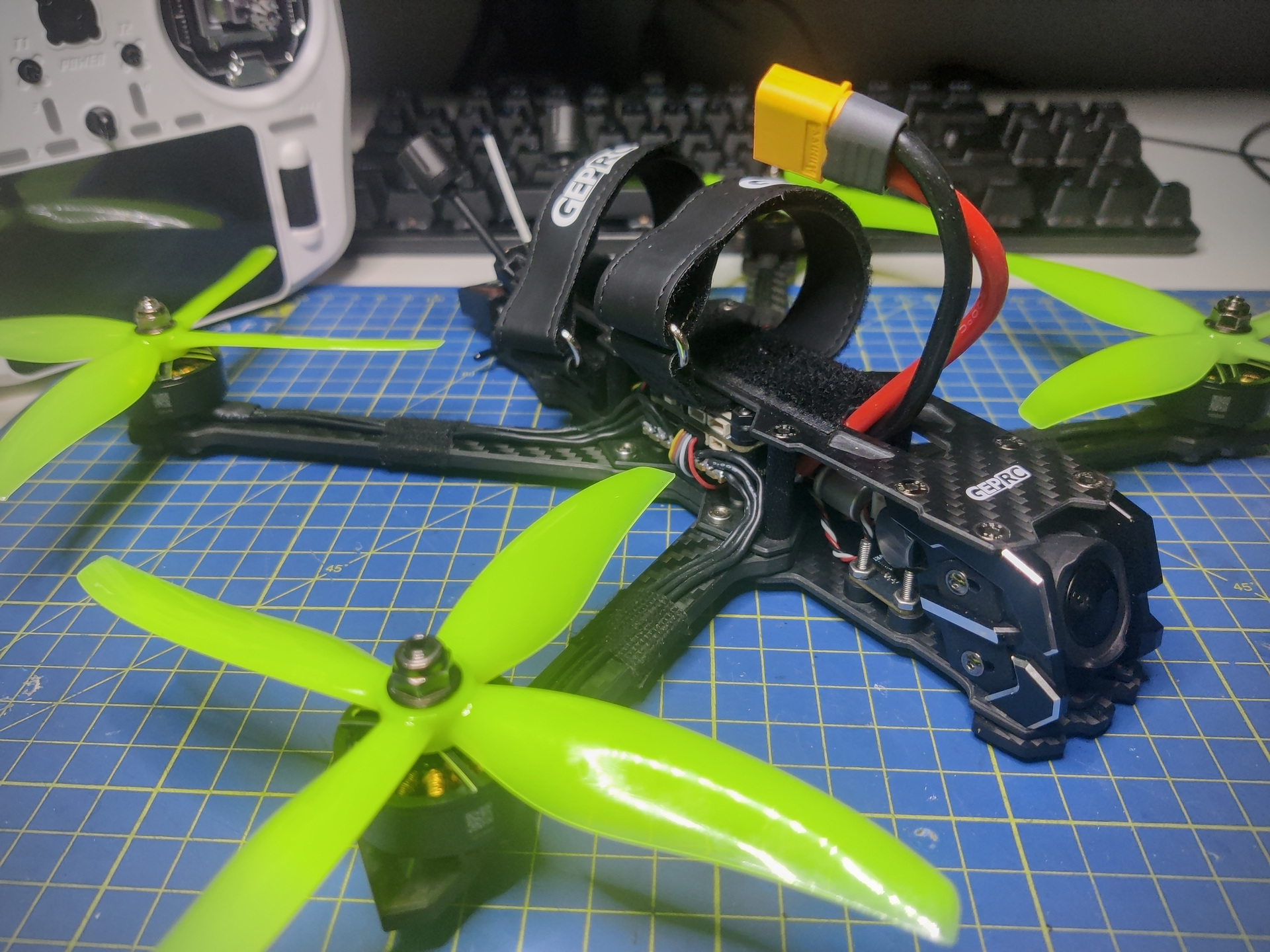
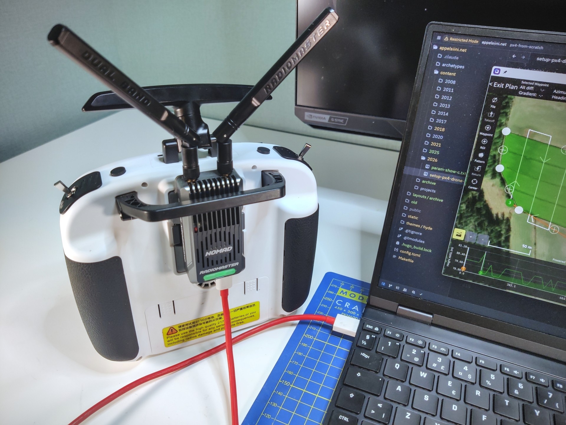
Hardware
The flight controller is a MicoAir743v2. It is a standard 30.5mm x 30.5mm mount controller and also has a build target for PX4.
I used the Nomad Gemini Xrossband ExpressLRS Module but any external module will do. You could fly without an external TX module, but it is required for connecting to the ground control station via USB.
Radio Setup
Using an external radio module requires you to change to External RF in
the model setup.
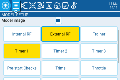
Additionally there are two main things to configure in the transmitter.
MAVLink mode
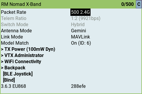
Run the ExpressLRS script in the transmitter. You can find it from the SYS
menu. Make sure packet rate is 500 2.4G and link mode is MAVLink. It
should also automatically change the telemetry ratio to 1:2 (9921 bps).
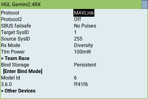
Go to the other devices menu and also change the receiver RC protocol to MAVLink.
Now they should talk MAVLink over ELRS with each other.
Flight modes
There will be seven different flight modes controlled by three physical switches: SA, SC and SB. Additionally the SF switch is used as panic recovery if your brain stops functioning. The idea is that left side has the simple flight modes. Moving to the right, complexity increases, and the rightmost switch is the panic button.
These are flight modes I personally prefer. I use the same switch layout and flight modes also with fixed wings.
| Switch | Mode | Notes | Logical Switch |
|---|---|---|---|
| SA↑ | Stabilized | Active when SB and SC are center (-) | L10 |
| SA- | Acro | Active when SB and SC are center (-) | L11 |
| SA↓ | Manual | Active when SB and SC are center (-) | L12 |
| SC↑ | Mission | Overrides SA | L13 |
| SC↓ | Offboard | Overrides SA | L14 |
| SB↑ | Hold | Overrides SA and SC | L15 |
| SB↓ | RTH/RTL | Overrides SA and SC | L16 |
| SF↓ | Panic | Overrides SA, SC and SB | L17 |
PX4 firmware does not have a dedicated panic recovery. I currently use position hold as a kludgish alternative.
Killswitch
When first hitting a tree it might come as a surprise that unlike with iNav or Betaflight the PX disarm switch will not kill the motors. That is because disarming is allowed only after landing. Your drone will be hanging in the tree with propellers spinning and there is nothing you can do.
PX4 does have a killswitch but you cannot configure it to use the same channel as arming. My solution for this is switch panic and disarm at the same time.
| Switch | Action | Notes | Logical Switch |
|---|---|---|---|
| SE↑ | Disarm | Works only after landing | |
| SE↓ | Arm | ||
| SE↑ SF↓ | Kill motors | Panic + Disarm == Kill, kill, kill | L19 |
This will not mess with my muscle memory because iNav and Betaflight setups will still disarm from the SE switch.
But how?
Configuring your radio to handle all this can be done in several ways. I chose the Programmer Way (tm) and used logical switches. The 0.1 second delay is there to avoid announcing a flight mode when SB or SC jumps over the center position.
You can configure this either by using the transmitter menus or by using the EdgeTX Companion software. I use the latter since it is much faster to use.
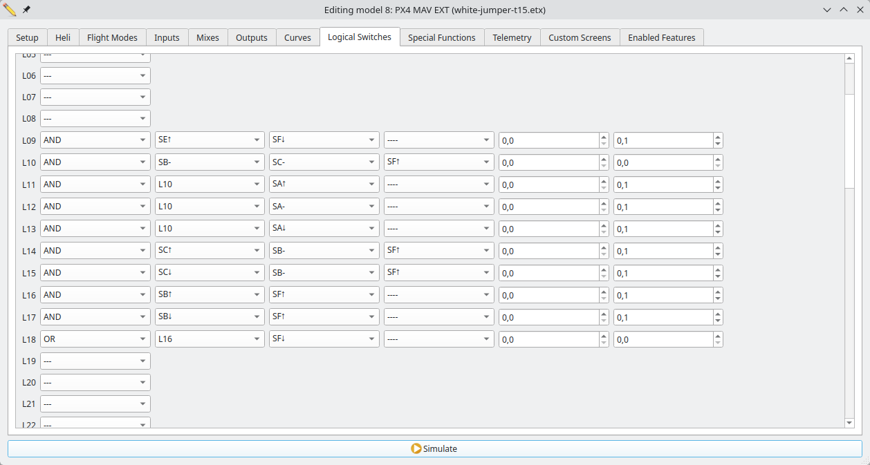
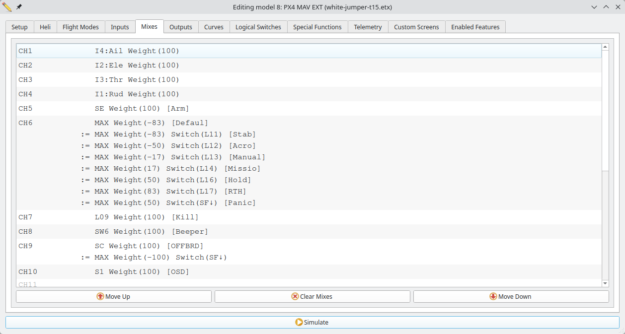
Logical switches are used to override the channel 6 output via mixes. This is what the flight controller reads to set the flight mode. Since offboard mode is not an actual flight mode in PX4, it is enabled using channel 9.
From the image you can also see channel 5 is used for arming, channel 7 for beeper and channel 8 for configuring the OSD.
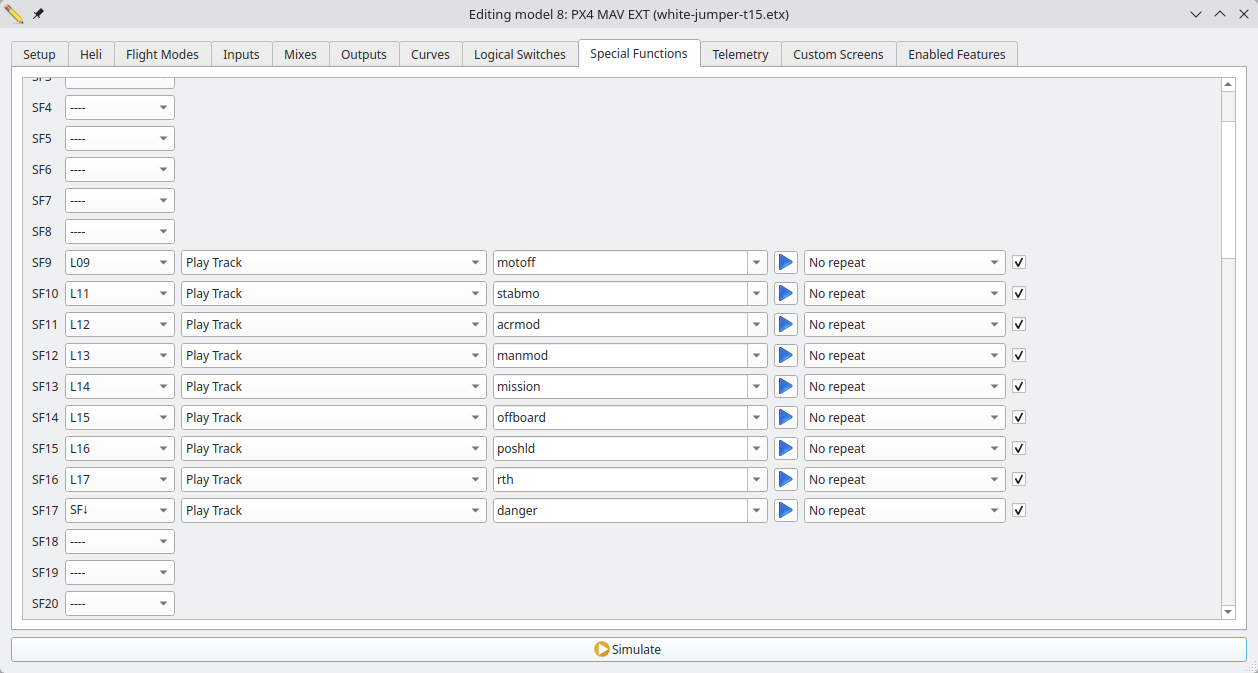
The flight mode announcements are done using special functions tied to logical switches.
If you have a Jumper T15 you can download above settings from
Firmware
Build
The default build of PX4 includes everything and the kitchen sink. I want to disable some features and also add support for MSP OSD. These instructions assume you have already set up the build environment.
$ git clone https://github.com/PX4/PX4-Autopilot.git --recursive
$ cd PX4-Autopilot
$ make micoair_h743-v2_default boardconfig
After changing the settings you can check the changes with git diff ..
$ git diff .
diff --git a/boards/micoair/h743-v2/default.px4board b/boards/micoair/h743-v2/default.px4board
index 320f1d29e9..f828f2ad1c 100644
--- a/boards/micoair/h743-v2/default.px4board
+++ b/boards/micoair/h743-v2/default.px4board
@@ -33,7 +33,8 @@ CONFIG_DRIVERS_POWER_MONITOR_INA238=y
 CONFIG_DRIVERS_POWER_MONITOR_VOXLPM=y
 CONFIG_DRIVERS_PPS_CAPTURE=y
 CONFIG_DRIVERS_PWM_OUT=y
-CONFIG_COMMON_RC=y
+CONFIG_DRIVERS_RC_CRSF_RC=y
+CONFIG_DRIVERS_RC_INPUT=y
 CONFIG_COMMON_RPM=y
 CONFIG_DRIVERS_SMART_BATTERY_BATMON=y
 CONFIG_DRIVERS_TAP_ESC=y
@@ -54,7 +55,6 @@ CONFIG_MODULES_EVENTS=y
 CONFIG_MODULES_FLIGHT_MODE_MANAGER=y
 CONFIG_MODULES_FW_ATT_CONTROL=y
 CONFIG_MODULES_FW_AUTOTUNE_ATTITUDE_CONTROL=y
-CONFIG_MODULES_FW_POS_CONTROL=y
 CONFIG_MODULES_FW_RATE_CONTROL=y
 CONFIG_MODULES_GIMBAL=y
 CONFIG_MODULES_GYRO_CALIBRATION=y
@@ -105,3 +105,4 @@ CONFIG_SYSTEMCMDS_UORB=y
 CONFIG_SYSTEMCMDS_USB_CONNECTED=y
 CONFIG_SYSTEMCMDS_VER=y
 CONFIG_SYSTEMCMDS_WORK_QUEUE=y
+CONFIG_ARCH_CHIP_STM32H7=y
After the build finishes you can see how much memory is being used.
$ make micoair_h743-v2_default -j8
...
Memory region         Used Size  Region Size  %age Used
        ITCM_RAM:           0 B        64 KB      0.00%
           FLASH:     1765492 B      1792 KB     96.21%
       DTCM1_RAM:           0 B        64 KB      0.00%
       DTCM2_RAM:           0 B        64 KB      0.00%
        AXI_SRAM:       53684 B       512 KB     10.24%
           SRAM1:           0 B       128 KB      0.00%
           SRAM2:           0 B       128 KB      0.00%
           SRAM3:           0 B        32 KB      0.00%
           SRAM4:           0 B        64 KB      0.00%
          BKPRAM:           0 B         4 KB      0.00%
Flash
Flashing is best done using a USB cable.
$ make micoair_h743-v2_default upload
...
Bootloader version: PX4BLv1.15.4g
Sn: 003d001f3233510d33353834
Chip: 20036450
Family: STM32H7[4|5]x
Revision: V
Flash: 1966080 bytes
Windowed mode: False

Erase  : [====================] 100.0%
Program: [====================] 100.0%
Verify : [====================] 100.0%
Rebooting. Elapsed Time 25.219
You can now connect to the NuttX shell and configure the flight controller.
$ ./Tools/mavlink_shell.py /dev/ttyACM0
NuttShell (NSH) NuttX-11.0.0
nsh>
nsh> ver all
HW arch: MICOAIR_H743_V2
PX4 git-hash: 24bbf5efd90335d7533f6769db7ee3d23a0e7aa1
PX4 version: 1.17.0 40 (17891392)
PX4 git-branch: main
OS: NuttX
OS version: Release 11.0.0 (184549631)
OS git-hash: 29450774d75a2ad4748ac93b2d8759f1ada48883
Build datetime: Mar 20 2026 17:48:19
Build uri: localhost
Build variant: default
Toolchain: GNU GCC, 13.2.1 20231009
PX4GUID: 000600000000333538343233510d003d001f
MCU: STM32H7[4|5]xxx, rev. V
...
Configure
RC Input
First thing to configure is the RC input. Since we are using MAVLink over ELRS,
plug the receiver into TELEM1 and not the RC port where it usually goes.
Change RC input protocol to CRSF. The default is auto but explicitly setting it to
the desired protocol is a safer option. Also change the TELEM1 serial baud to
460800 to match the RX when running in MAVLink mode. MAV_0 rate should be
9600.
These settings approximately match the transmitter which was configured for 500Hz packet rate resulting in 9921bps MAVLink rate.
nsh> param set RC_INPUT_PROTO 6
nsh> param set SER_TEL1_BAUD 460800
nsh> param set MAV_0_RATE 9600
RC Input Channels
Map the four primary flight control axes to RC channels in PX4. This is the standard AETR channel order.
nsh> param set RC_MAP_ROLL 1
nsh> param set RC_MAP_PITCH 2
nsh> param set RC_MAP_THROTTLE 3
nsh> param set RC_MAP_YAW 4
nsh> param save
nsh> reboot
Connect the flight controller to USB and start QGC to make sure channels are
mapped correctly. You should see matching stick movement in the Radio tab.
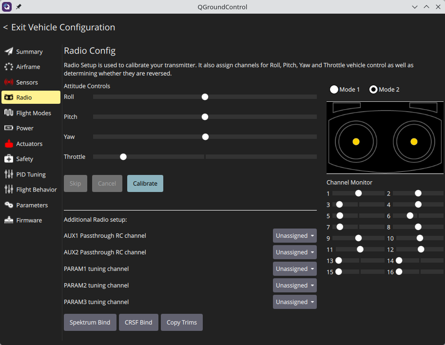
If everything is ok click Calibrate button to calibrate the sticks. Make sure
to also calibrate all the switches or you will have mysterious problems later.
Switch Channels
Set transmitter channels. Channel 5 for arming and channel 6 for flight mode.
nsh> param set RC_MAP_ARM_SW 5
nsh> param set RC_MAP_FLTMODE 6
Flight Modes
Flight modes are: stabilized, acro, manual, mission, position hold, and RTH. These match the radio setup explained above. Offboard mode is special. PX4 does not consider it a flight mode and instead activates the mode from a separate channel 9.
nsh> param set COM_FLTMODE1 8
nsh> param set COM_FLTMODE2 6
nsh> param set COM_FLTMODE3 0
nsh> param set COM_FLTMODE4 3
nsh> param set COM_FLTMODE5 4
nsh> param set COM_FLTMODE6 5
nsh> param set RC_MAP_OFFB_SW 9
nsh> param save
nsh> reboot
Make sure flight modes work as expected. You can listen to vehicle status
in the NuttX shell. Look for changes in nav_state parameter when you flip the
switches.
nsh> listener vehicle_status -r 1
Or use the QGC statusline.

Motors
Attach the battery. The motors will beep.
In the Actuators menu, set motor protocol to DShot300. With PX4 there really
is no point in using DShot600. Then click Identify & Assign Motors and motors
will spin one by one. Click on the image to confirm which motor was spinning.
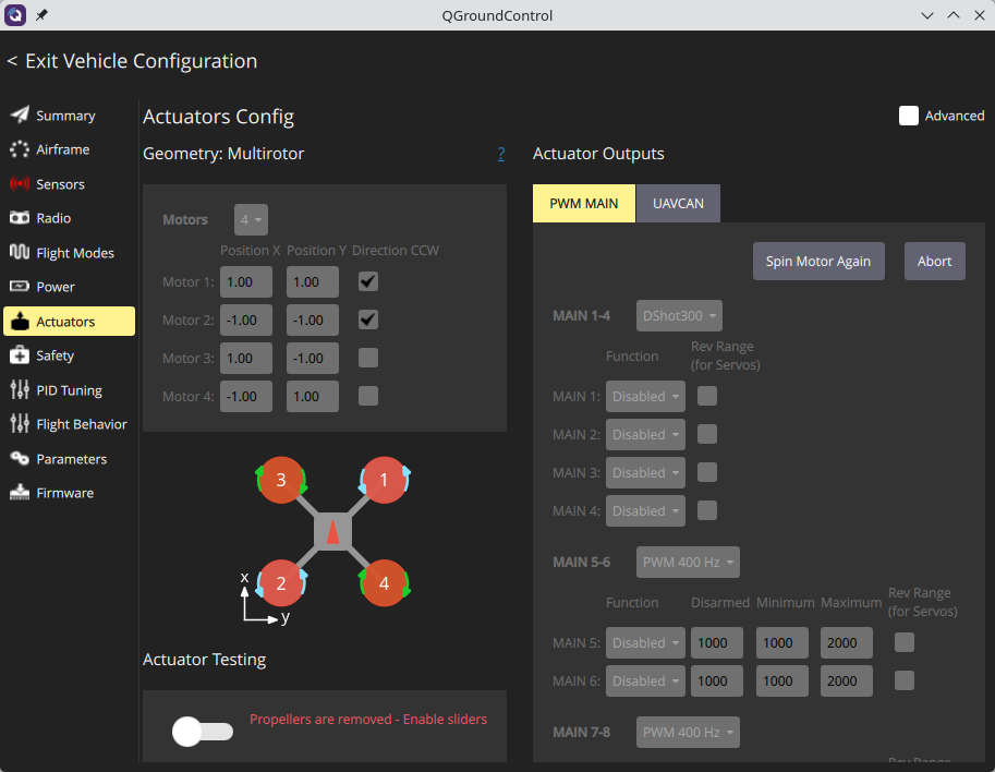
Also make sure the motor is spinning in the correct direction. The direction
should match the image in QGC. If not, you can either swap two motor wires
or change it in the Actuators menu.
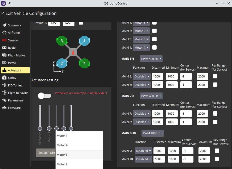
Motors won’t beep anymore. Now you are ready to calibrate.
Calibrate
Magnetometer calibration requires rotating the quad 360 degrees around every axis. While possible with USB, it will be cumbersome. MicoAir flight controller has Bluetooth support which makes the calibration process easier.
Configure Bluetooth
First, turn on Bluetooth and find the address of your flight controller.
$ bluetoothctl
[bluetooth]# power on
[bluetooth]# scan on
[bluetooth]# devices
Device 39:54:9E:52:09:D1 MicoAir743v2-78387

[bluetooth]# pair 39:54:9E:52:09:D1
[bluetooth]# trust 39:54:9E:52:09:D1
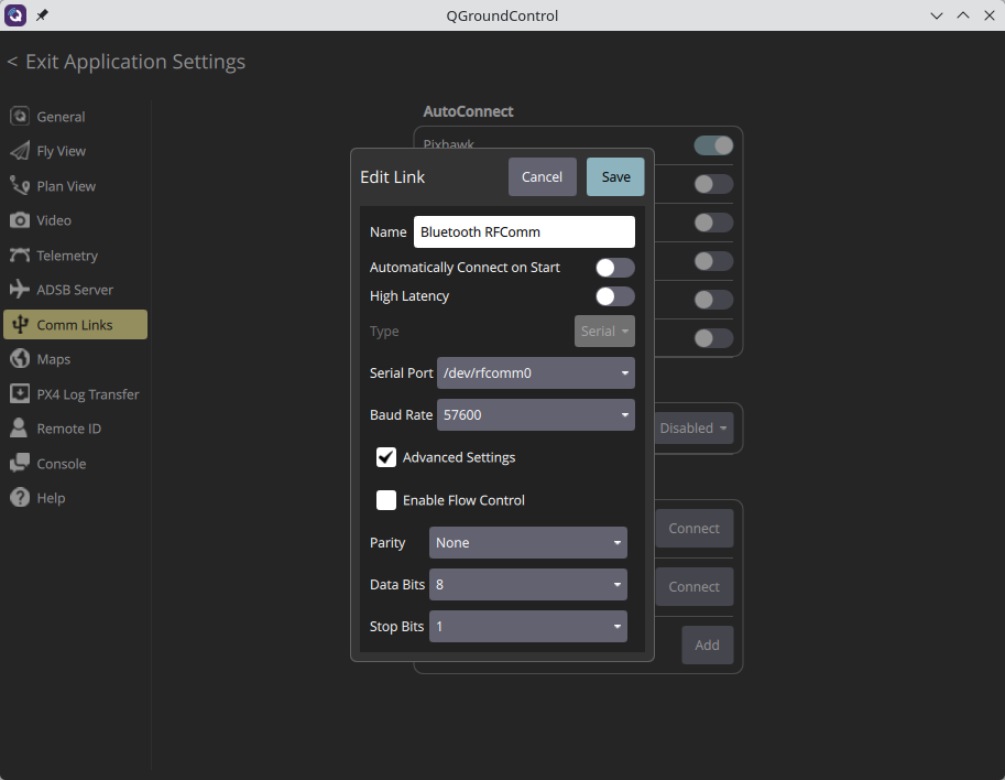
I was not able to make QGC connect directly to this Bluetooth device. Instead I had to make a virtual serial device which is bound to the Bluetooth device.
$ sudo rfcomm bind 0 39:54:9E:52:09:D1 1
$ stty -F /dev/rfcomm0
speed 57600 baud; line = 0;
min = 0; time = 0;
-brkint -icrnl -imaxbel
-opost
-isig -icanon -iexten -echo
In QGC, add a new serial connection Comm settings -> Add new link. I call it Bluetooth RFComm. You can now wirelessly connect to the FC with this connection.
Calibrate sensors
Connect to the Bluetooth RFComm and go to Sensors tab. Calibrate all the sensors
one by one. Follow the instructions on the screen. Instructions are pretty self-explanatory.
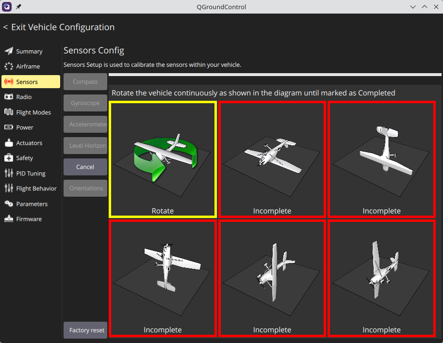
After any major model rebuild you should calibrate the sensors again. Especially the magnetometer is susceptible to small changes in magnetic fields.
Test Flight
Before attempting autonomous flight, this would be the time to make a test flight. Make sure all the flight modes work. Triple check position hold and return to home really work. If not, double check magnetometer and flight controller orientations and redo calibration.
Configure Transmitter USB
Connect the external TX module to your computer using USB. In QGC, add a new
serial connection. I call the connection Transmitter USB but any name will
do.
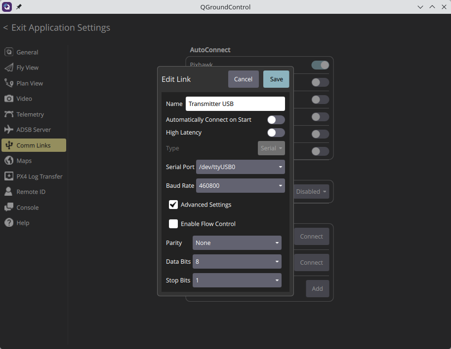
You can now connect to the FC with this connection.
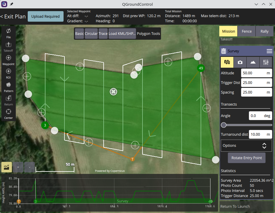
You can now configure the drone or even plan missions wirelessly. Congrats, the first autonomous flight is pretty exciting.
Additional Reading
See the ExpressLRS MAVLink documentation for a more in-depth explanation of how to configure MAVLink over ELRS. If you prefer a video, Painless360 has a great clip on the same subject.
See How to Calibrate a Magnetometer for theory and example code about how magnetometer calibration works.